In this tutorial, we will use shaders for scaling and post-processing a 2D PyGame game. We will not cover actual 3D graphics or rendering 2D sprites, but use OpenGL to display and process a PyGame surface as the final rendering step after your drawing code has finished.
This tutorial should be a bit easier to follow than the last one about asyncio. This tutorial is based on the moderngl library, Python 3.6, and PyGame 1.9. If you are familiar with Python, PyGame, and a bit of C or other languages with curly braces, you should be able to follow this tutorial without any prior knowledge of OpenGL or shaders. After introducing a simple example program, we will look at a version based on OpenGL, and explain what the new OpenGL bits do. Then we will gradually build more complex iterations of the shaders, and arrive at a retro-CRT effect with rounded corners and scan lines.
There are other ways to do these things in PyGame, but using OpenGL together with PyGame surfaces gives you both speed and flexibility, at the expense of some boilerplate code. With the upcoming 2.0.0 release of PyGame, you will get some new display/rendering features based on SDL2, but they are not as flexible as writing your own custom shaders. You can also scale up surfaces with pygame.stransform.scale() and post-process with numpy or by iterating over pixels with for-loops, but that is not as fast as doing it on the GPU.
Let's start by looking at the very simple example program without any openGL features:
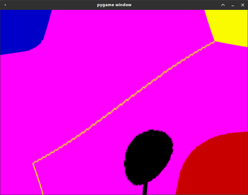
import pygame
from pygame.locals import *

pygame.init()

RES=(160, 120)
FPS=30
clock = pygame.time.Clock()
screen = pygame.display.set_mode(RES, DOUBLEBUF)

done=False

while not done:
    for event in pygame.event.get():
        if event.type == QUIT:
            done = True

    screen.fill((255,0,255))
    pygame.draw.circle(screen, (0,0,0), (100,100), 20)
    pygame.draw.circle(screen, (0,0,200), (0,0), 10)
    pygame.draw.circle(screen, (200,0,0), (160,120), 30)
    pygame.draw.line(screen, (250,250,0), (0,120), (160,0))

    pygame.display.flip()
    clock.tick(FPS)

pygame.quit()
This program just re-draws three circles and a line on the screen every frame. It is just a placeholder for whatever game logic you have. It looks like this:
We will retrofit that simple 2D program to use GL to display this surface scaled up to a higher resolution, with a nice shader to add a CRT post-processing effect.
Now let's look at the first improved version program piece by piece. Instead of drawing to a display surface created by pygame.display.set_mode(), we create our own display surface, copy the contents to a texture, and render that texture on two triangles with OpenGL.
import struct
import pygame
from pygame.locals import *

import moderngl
The program starts with a bunch of imports. We import pyGame as before, but also struct, a module that lets us encode python objects as binary data, and modernGL, an openGL wrapper built for Python 3 and OpenGL 4. ModernGL doesn't expose the old-style API with glBegin(), glVertex3f(), and glEnd(). If you're writing a new application based on OpenGL 4, you don't need to use the legacy API. If you want to use the legacy API, or Python 2.7, then you have to use the PyOpenGL library instead (and you need to find a different tutorial for that).
pygame.init()

FPS=30
clock = pygame.time.Clock()

VIRTUAL_RES=(160, 120)
REAL_RES=(800, 600)

screen = pygame.Surface(VIRTUAL_RES).convert((255, 65280, 16711680, 0))
pygame.display.set_mode(REAL_RES, DOUBLEBUF|OPENGL)
This bit is almost the same as above. Instead of creating a display surface, we create a regular surface. The surface creation parameters specify a 24-bit RGB colour mode. It might become clearer if you write it out in binary: (255, 65280, 16711680, 0) is equal to (0b11111111, 0b1111111100000000, 0b111111110000000000000000, 0b0). This format is what our OpenGL shader expects.
The screen is set to OPENGL mode, at a higher resolution than our drawing surface.
In the next bit we create a "context" with modernGL, which is kind of a handle to a drawing area managed by the GPU. Then we save the coordinates of the triangles we want to draw.
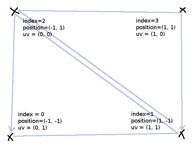
ctx = moderngl.create_context()

texture_coordinates = [0, 1,  1, 1,
                       0, 0,  1, 0]

world_coordinates = [-1, -1,  1, -1,
                     -1,  1,  1,  1]

render_indices = [0, 1, 2,
                  1, 2, 3]
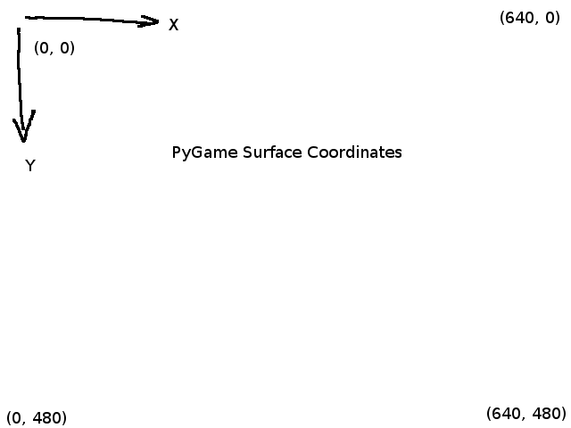
OpenGL has a coordinate system which is very different from the one in PyGame. Let's assume for the sake of simplicity that the window size is 640x480 (VGA resolution). In PyGame, the top-left pixel of the window is (0, 0), and the bottom-right is (639, 479). Coordinates on windows, screens or surfaces in general in pyGame are positive integers.
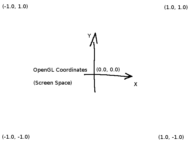
In OpenGL, coordinates are usually floating point numbers, and screen coordinates go from (-1, -1) in the bottom-left to (+1, +1) in the top-right.
Texture coordinates in OpenGL are different from screen coordinates. That's an important difference to pyGame, where surfaces, which are kind of like textures, are also used to represent the screen. Texture coordinate space is also called uv-space, to distinguish it from world space, model space, or screen space, which have x, y, and z dimensions.
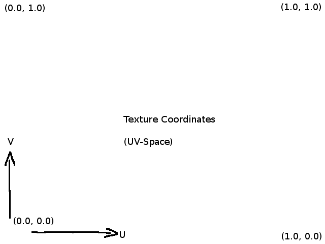
In order to display the contents of our pyGame surface with OpenGL, we must map the top-left of our surface, which is (0, 0) in pyGame coordinates, to (-1.0, 1.0). If we just copy the RGB data of our pyGame surface into an OpenGL texture, it will be flipped because the raw data will be interpreted upside-down, in the coordinate system of OpenGL textures. To counteract this, we need to map the top-left OpenGL screen space coordinates (-1.0, 1.0) to the texture uv-coordinates (0.0, 0.0).
The variables texture_coordinates and world_coordinates are lists of (x, y) or (u, v) pairs of coordinates, where the coordinate pairs for world/screen position correspond to the coordinate pairs for texture at the same place. (World and screen space are the same in our example, because we don't do any 3D perspective transformation.)
The list render_indices is used to describe the triangles to render. This way we don't have to write the same point twice, and we can separate the shape of our triangles from the topology. This can come in especially handy with large 3D models where every vertex is shared by multiple triangles, or when you want to deform a mesh without changing the topology.
Now we need to write some shaders to colour in the two triangles. It roughly works like this: First, a vertex shader gets the vertex coordinates and texture coordinates, and computes the position of the vertex in the world. Then, the fragment shader iterates over the triangles, pixel by pixel, and computes the colour of the triangle at that point. The result of the vertex shader for the corners of the triangle is interpolated as some kind of weighted average. Because of this interpolation, the texture coordinates that were copied by the vertex shader are interpolated as input for the fragment shader, and the fragment shader has the right coordinates to look up in the texture.
That was very high-level. I hope you get the gist of it. Shaders are written in GLSL, a language that looks like C, but isn't quite C. For one thing, GLSL has multiple named input and output parameters. The named outputs of the vertex shader correspond to inputs for the fragment shader with the same names. The output colour of the fragment shader is drawn on the screen.
We pass the shader programs to the program method as strings, and if there are any type or syntax errors, this method will throw an error at run-time. For now, just copy the shaders.
prog = ctx.program(
    vertex_shader='''
#version 300 es
in vec2 vert;
in vec2 in_text;
out vec2 v_text;
void main() {
   gl_Position = vec4(vert, 0.0, 1.0);
   v_text = in_text;
}
''',

    fragment_shader='''
#version 300 es
precision mediump float;
uniform sampler2D Texture;
in vec2 v_text;

out vec3 f_color;
void main() {
  f_color = texture(Texture,v_text).rgb;
}
''')
The vertex shader just takes the x/y position of the input and outputs a vector with the z and scaling component set to default values, and copes the texture coordinates to they are available to the fragment shader. The fragment shader takes the texture coordinates and looks up the pixel value in a texture. As explained above, the texture coordinates are interpolated fr each pixel based on the positions of the vertices, so the input variable v_text is not only set to the texture coordinates from our list.
We're back to Python code now. In this part of the program, we serialise the data into bytestrings and copy it into graphics memory: The vertex coordinates, the texture coordinates, the indices, and the texture.
screen_texture = ctx.texture(
    VIRTUAL_RES, 3,
    pygame.image.tostring(screen, "RGB", 1))

screen_texture.repeat_x = False
screen_texture.repeat_y = False

vbo = ctx.buffer(struct.pack('8f', *world_coordinates))
uvmap = ctx.buffer(struct.pack('8f', *texture_coordinates))
ibo= ctx.buffer(struct.pack('6I', *render_indices))

vao_content = [
    (vbo, '2f', 'vert'),
    (uvmap, '2f', 'in_text')
]

vao = ctx.vertex_array(prog, vao_content, ibo)
The render() function will be called instead of pygame.display.flip(). We take the contents of our screen surface, and copy them over into the texture. Then we render that texture and update the screen. The rest of the program is the same as the original.
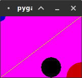
def render():
    texture_data = screen.get_view('1')
    screen_texture.write(texture_data)
    ctx.clear(14/255,40/255,66/255)
    screen_texture.use()
    vao.render()
    pygame.display.flip()

#MAIN LOOP

done=False

while not done:
    for event in pygame.event.get():
        if event.type == QUIT:
            done = True

    screen.fill((255,0,255))
    pygame.draw.circle(screen, (0,0,0), (100,100), 20)
    pygame.draw.circle(screen, (0,0,200), (0,0), 10)
    pygame.draw.circle(screen, (200,0,0), (160,120), 30)
    pygame.draw.line(screen, (250,250,0), (0,120), (160,0))

    render()
    clock.tick(FPS)
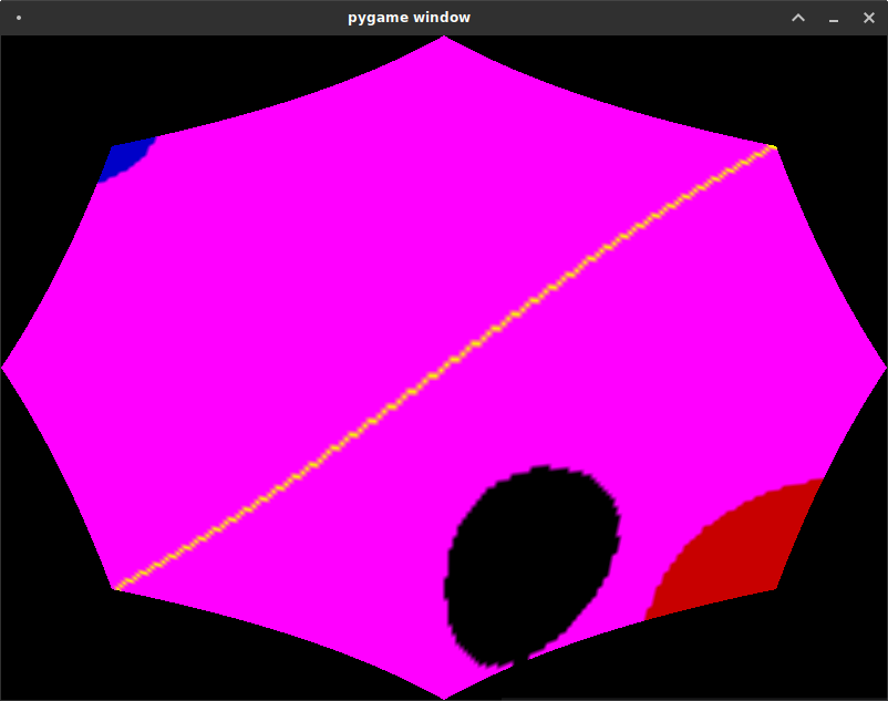
The resulting pyGame window should render something like this:
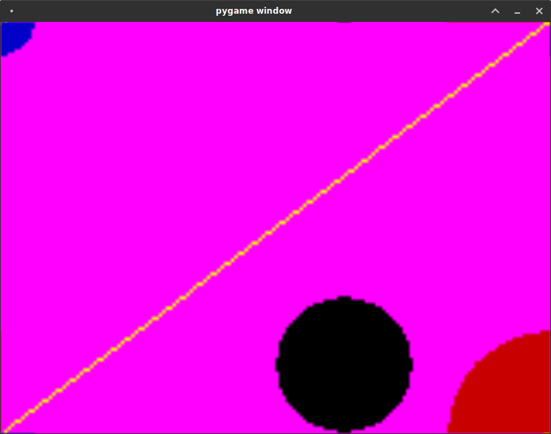
This is just scaling up the surface with GL though, with no fancy post-processing.
Let's fix that. First, we need to factor out our GLSL code and load it from separate files. This way we can use the GLSL syntax highlighting of our text editor. So please copy the shader code for the vertex and fragment shaders into separate ".glsl" text files, save them somewhere next to your python program, and load them like this:
prog = ctx.program(
    vertex_shader=open("PATH_TO_YOUR_VERTEX_SHADER.glsl").read(),
    fragment_shader=open("PATH_TO_YOUR_FRAGMENT_SHADER.glsl").read()
)
Now we can try to build a sweet CRT+scanline effect. To get the look of rounded corners, parts of the screen near the corners, and far away from the main axes of the screen, should be distorted. To get the "pushed-in" round corner effect, you need to sample the further out in these areas.
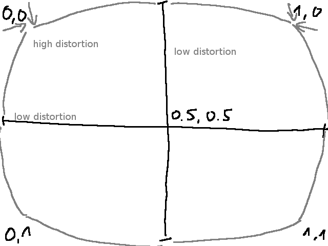
That means the further we are from the horizontal center line, the more should we distort horizontally (by sampling the texture further put), and the further we are from the vertical center line, the more we should distort vertically, but the center of the screen should be a fixed point.
The transformations in this shader are based on the distance from the center of the screen in texture-space at (0.5, 0.5). We scale the distance from the center in the x-direction by the distance from the center in the y-direction, and vice versa.
#version 300 es
precision mediump float;
uniform sampler2D Texture;

out vec4 color;
in vec2 v_text;
void main() {
  vec2 center = vec2(0.5, 0.5);
  vec2 off_center = v_text - center;

  off_center.x*=(1.0+abs(off_center.y));
  off_center.y*=(1.0+abs(off_center.x));

  vec2 v_text2 = center+off_center;

  color = vec4(texture(Texture, v_text2).rgb, 1.0);
}
This looks a bit awkward, so we check if we land outside of the bounds of the texture, and if so, we set the colour to black.
#version 300 es
precision mediump float;
uniform sampler2D Texture;

out vec4 color;
in vec2 v_text;
void main() {
  vec2 center = vec2(0.5, 0.5);
  vec2 off_center = v_text - center;

  off_center.x*=(1.0+abs(off_center.y));
  off_center.y*=(1.0+abs(off_center.x));

  vec2 v_text2 = center+off_center;

  color = vec4(texture(Texture, v_text2).rgb, 1.0);

  if (v_text2.x > 1.0 || v_text2.x < 0.0 ||
      v_text2.y > 1.0 || v_text2.y < 0.0){
    color=vec4(0.0, 0.0, 0.0, 1.0);
  }
}
This is basically what we want, but the shape is not quite right. Let's simplify the code first.
#version 300 es
precision mediump float;
uniform sampler2D Texture;

out vec4 color;
in vec2 v_text;
void main() {
  vec2 center = vec2(0.5, 0.5);
  vec2 off_center = v_text - center;

  off_center*=(1.0+abs(off_center.yx));

  vec2 v_text2 = center+off_center;
  color = vec4(texture(Texture, v_text2).rgb, 1.0);

  if (v_text2.x > 1.0 || v_text2.x < 0.0 ||
      v_text2.y > 1.0 || v_text2.y < 0.0){
    color=vec4(0.0, 0.0, 0.0, 1.0);
  }
}
Now we raise the distance from the center to the 2.5th power to make the distortion smaller near the center lines and relatively larger near the corners.
#version 300 es
precision mediump float;
uniform sampler2D Texture;

out vec4 color;
in vec2 v_text;
void main() {
  vec2 center = vec2(0.5, 0.5);
  vec2 off_center = v_text - center;

  off_center *= 1.0 + 0.8 * pow(abs(off_center.yx), vec2(2.5));

  vec2 v_text2 = center+off_center;

  color = vec4(texture(Texture, v_text2).rgb, 1.0);

  if (v_text2.x > 1.0 || v_text2.x < 0.0 ||
      v_text2.y > 1.0 || v_text2.y < 0.0){
    color=vec4(0.0, 0.0, 0.0, 1.0);
  }
}
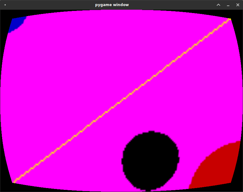
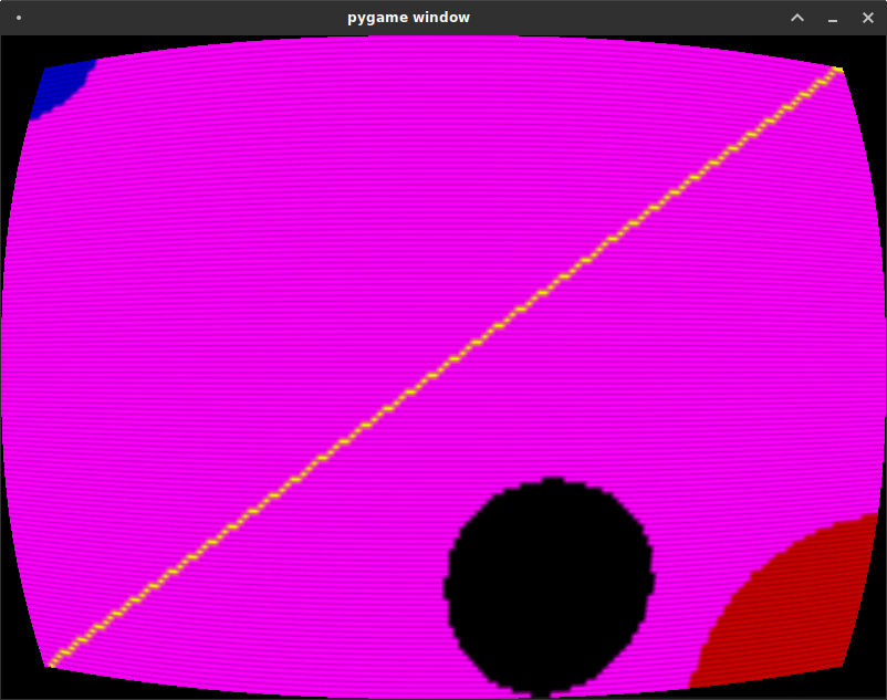
This looks pretty! Now to add scan lines. We use textureSize(Texture,0) to get the size of the texture in pixels instead of the uv-space from 0.0 to 1.0. With fract(), we can get the fractional part of the pixel coordinates, and darken a portion of each "pixel".
#version 300 es
precision mediump float;
uniform sampler2D Texture;

out vec4 color;
in vec2 v_text;
void main() {
  vec2 center = vec2(0.5, 0.5);
  vec2 off_center = v_text - center;

  off_center *= 1.0 + 0.8 * pow(abs(off_center.yx), vec2(2.5));

  vec2 v_text2 = center+off_center;

  color = vec4(texture(Texture, v_text2).rgb, 1.0);

  if(fract(v_text2.y * float(textureSize(Texture,0).y))>0.75)
    color.rgb*=0.5;

  if (v_text2.x > 1.0 || v_text2.x < 0.0 ||
      v_text2.y > 1.0 || v_text2.y < 0.0){
    color=vec4(0.0, 0.0, 0.0, 1.0);
  }
}

This image looks a bit artefact-y. Instead of abrupt on-off darkening between scan lines, let's use a function that gradually darkens at the boundary between lines. The function defined as f(x) = min(x, 1-x), is always below 0.5, and has minima around whole numbers, and maxima at whole numbers plus one half, furthest away from whole numbers. We can use it to implement a nice smooth and symmetric scanline effect.
#version 300 es
precision mediump float;
uniform sampler2D Texture;

out vec4 color;
in vec2 v_text;
void main() {
  vec2 center = vec2(0.5, 0.5);
  vec2 off_center = v_text - center;

  off_center *= 1.0 + 0.8 * pow(abs(off_center.yx), vec2(2.5));

  vec2 v_text2 = center+off_center;

  if (v_text2.x > 1.0 || v_text2.x < 0.0 ||
      v_text2.y > 1.0 || v_text2.y < 0.0){
    color=vec4(0.0, 0.0, 0.0, 1.0);
  } else {
    color = vec4(texture(Texture, v_text2).rgb, 1.0);
    float fv = fract(v_text2.y * float(textureSize(Texture,0).y));
    fv=min(1.0, 0.8+0.5*min(fv, 1.0-fv));
    color.rgb*=fv;
  }
}